Numa Compact X SE
User manual## Introduction
The Numa Compact is an incredibly powerful musical instrument, packed in a stylish and slim cabinet, based on a totally new technology and updated user interface. The keyboard includes an Aftertouch control and together with the programmable Sticks, allows to have a total control of the musical performance. The new sound engine is capable of 200 notes of max polyphony and it includes two independent sections (Lower & Upper) with over 148 sounds, organized in 8 Sound Banks, assignable to any portion of the keyboard, in Layer or Split mode. The 1GB (flash memory) sounds are further enhanced by 2 effects post-processors (Fx1-Fx2) each one with a double internal architecture, for a total of 6 independent effects at once.

## Power and connections
### Power connection
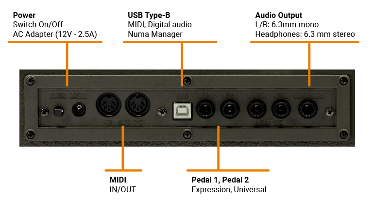
Use the power adapter supplied with the device to connect the Numa Compact to the power socket (or use the USB connection). Switch the unit on by using the power button next to the power plug of the Numa Compact, set the main Volume, Bass and Treble controls to the half position and the Mastering control to zero-minimum (the function will be explained later on this manual) to avoid excessive output power and allow the internal speakers to play with a correct dynamic range.
#### USB power
The instrument can also be powered by USB, using a shielded quality certified cable and providing that the computer has enough power and not too many devices are powered through the same USB port.
When the instrument is USB powered, the internal amplification system is disconnected.
In case of weak or unstable connection, use the traditional power (see previous paragraph).

### Expression / Universal pedals
Connect the (optional) pedal or pedals to the related sockets, labelled Ped1 and Ped2; at the socket labelled PED1 you can plug in the Studiologic FP/50 or VP/27 pedal, typically for volume-expression controls. To the PED2 socket you can plug either a single swicth pedal, a volume-expression pedal or the custom triple pedal SLP3-D, as explained in the related chapter.
### Audio output
If you want to use external amplification systems, or record the instruments sounds, connect the Left and Right audio outputs to the inputs of your mixing desk or amplifier, or to your computer audio board inputs, using suitable cables.
### Headphones
The Headphones output can be used with an headphones set or as an extra audio auxiliary output, according to the setting of the related GLOBAL edit function (explained in this manual). As an auxiliary audio out, you can use this plug to connect the instrument to a subwoofer or an additional amplification system, while the L/R outputs are still available for recording or other audio connections.
### Volume
When you use the Numa Compact for the first time, we recommend you to turn the Volume knob on the Output section to not more than half way between 0 and Full. While you are playing you can adjust the volume according to the selected sounds. Adjusting the Volume knob will effect all audio and headphone outputs at the same time.
To prevent hearing damage, you should – as with all audio devices – avoid using the Numa Compact at high volume for long periods.
### USB
For data transmission via USB, connect the Numa Compact to your computer with a USB cable. The first time you switch the Numa Compact on, it will be recognised by your computer automatically and the appropriate driver will be installed by the OS (cross compliant).
The USB also supports the transmission of digital audio.
## Panel - display and navigation

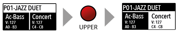
The main HOME display of the Numa Compact is the one shown at power on and it’s divided in 3 main areas: the top area shows the current Program number and name, the left and right lower areas are related to the Lower and Upper Sound sections, in SOUND mode, and to the Zone A and Zone B sections, in MIDI Mode.
Two differente navigation modes can be choosen in Global edit.
If you set the related parameter ADVANCED, the navigation works as follow:
- Press ***SOUND*** to show the *UPPER* and *LOWER* parts on the display.
- Press ***MIDI*** to show *Zone A* and *Zone B* on the display.
- Press ***LOWER (MIDI A)*** and ***UPPER (MIDI B)*** to enable or disable the audio parts and the MIDI zones.
- When the *SOUND* button is on, press it to move the focus from *UPPER* part to *LOWER* part and vice versa.
- When the *MIDI* button is on, press it to move the focus from *Zone A* to *Zone B* and vice versa.
- Press the **Encoder** to move the focus to the Program. A second press of the Encoder shows the list and press again so choose the Program.
With ADVANCED navigation, when you move a Sliders that control the SYNTH parameters, the display shows the changes of the related parametes.
The nine parameters are grouped into four display types:
- FILTER Cutoff and Resonance
- ADR Attack-Decay-Release of the Filter
- LFO Speed and Modulation Depth of the Filter Cutoff
- AR – Attack and Release of the AMP section
In the Filter, the Sustain level (frequency after decay) is approximated on the Decay value: by setting the Decay to maximum, the final Sustain level is reached with a very long time which allows you to simulate a maximum Sustain within certain times.
If you set the related parameter STANDARD, the navigation works as follow:
- Clicking on the Encoder: the focus will move to the 3 main positions: Programs, Lower, Upper.
- Pressing the Sound or MIDI buttons, the focus (cursor position) will be moved on top.
- Pressing Lower or Upper, the focus (cursor position) will be set to the related areas.
- When the focus is on the Program area, rotating the Encoder you will select the various Programs.
- When the focus is on the Lower/Upper areas, rotating the Encoder you will control the related volumes.
### Sound / MIDI
The two buttons marked SOUND and MIDI will toggle between the two related views and controls.
When the SOUND button is selected and lighted, the user can control the SOUND sections and selections, all related display, settings, edit pages and parameter settings.
When the MIDI button is selected and lighted, the display will show the status of the MIDI Zones A and B and the user can access to all available parameters, edit functions and values.
### Demo
The SOUND button can also be pressed for a longer time, to enable the eight DEMO songs (one for each sound BANK) to start playing in sequence; clicking on a SOUND BANK you can also select the related demo; at the end of it, the next demo song will start for the other BANKS, in a continuous cycling loop.
### Split
This button is a real time control of the SPLIT function, that is edited and controlled in all details by the GLOBAL EDIT function (Split Point) and PART EDIT function (Split Assign). This is a fast way to immediately enable and disable the SPLIT and play the UPPER and LOWER parts all over the keyboard, in layer mode without split.
As explained in the EDIT sections, the SPLIT button can also be used as a short cut to select the MIXER page, by keeping it pressed for a few seconds.
### Store / User Programs
The Numa Compact has 120 programmable memories called Programs, where you can store all SOUND, FX1/2 controls, amounts, functions, split points and all editable parameters also related to the MIDI ZONES, with a programmable NAME for each Program. The only non-storable functions are the VOLUME, BASS, TREBLE and MASTERING, since they are pure real-time controls, not related to a particular Program.
All Programs can be sent and received via USB, as explained in the related paragraph of this manual, in the GLOBAL EDIT section.
Press STORE to save all related settings.
## Sound banks and sound section

### Sound mode
In SOUND mode, with the related button selected and lighted, the 8 Sound banks can select the internal sounds, organized according to the Sound Bank names. Each Bank can have a variable number of sounds, organized in pages of 4 sounds for each one. Selecting a Bank, you will see on the display the sounds of that Bank, the current Sound Bank and total pages of sounds of the Bank (shown on the top right area of the display) and the selected sound, in reverse color.
To select another sound of the current Bank, rotate the encoder and all available sounds will be shown and selected in sequence, from the first to the last page of the Bank. The selection can be done during a temporary window (approx 5 seconds) and the last selected sound will be automatically memorized for each Bank. You can also click the Encoder to confirm the selection.
When you select a Bank, the focus will automatically go to the last selected Sound, to make the sound selection easier and faster. Thanks to this function, you will have an automatic setting of your preferred sounds for each Bank.

## Organ Engine

In an original tone wheel organ, 91 steel wheels with lobes rotate in front of a pick-up consisting of a permanent bar magnet and a spool. Because of the tone wheels shape, the magnetic field in the pick-up changes periodically and generates a sine wave.
With 8 different tone wheel shapes and 12 different gear trains 91 sine frequencies are generated. As in additive synthesis, the 91 frequencies are the base for creating different sound timbres. By means of a complex circuit lay out, the sound is mixed thru nine drawbars, allowing a tone wheel organ to create hundreds sound timbres from just 91 generated sine frequencies: more than 380 million timbres are theoretically possible. To generate a sound, Numa Compact SE uses physical modelling, a mathematical implementation of the tone wheel organ.
Thanks to the Modelling Technology, Numa Compact SE have been designed to give a wide variety of sounds, allowing to build combinations using the drawbars and all the related post effects: Vibrato, Chorus, Percussion with harmonics and decay controls, plus specific GLOBAL Edit pages to control features like the Key Click and Percussion separate volumes.
The sound generated by the Organ Model can be sent to the same Effects chain of all other Sound Banks, that can further enhance the quality of the sound, with all possible effects from the typical Rotary to the Drive, from Chorus to Delay and many more. The Organ Sound Bank includes this new clone of a Tone Wheel Organs with Drawbars controls, with the addition of accurately sampled Electronic and Classic-Pipe organs, in a complete variety of organ sounds of all kinds. The Organ sounds and all associated effects and post-processing can be Stored in each of the 120 available Programs.
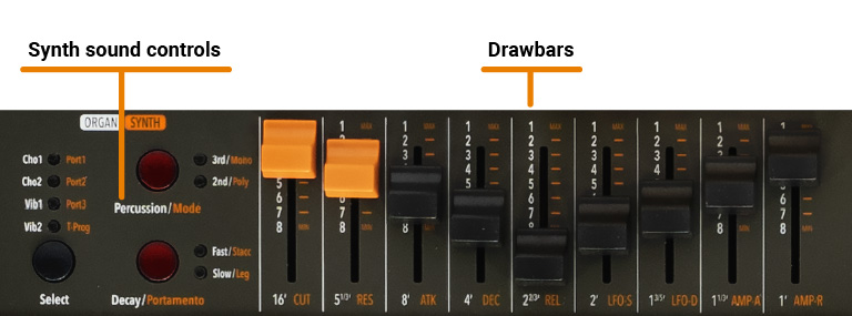
### Drawbars
Drawbars are a characteristic trait of a tone wheel organ, therefore we’ll explore them first; a Tonewheel Organ sound can be made of nine sine frequencies and each drawbar represents a harmonic of the scale related to the 8‘ stop of a pipe organ (drawbar 3) which is also called "native pitch".
| Drawbar | Feet |
|---------|------|
| 1 | 16'
| 2 | 5 1/3'
| 3 | 8'
| 4 | 4'
| 5 | 2 2/3' |
| 6 | 2' |
| 7 | 1 3/5' |
| 8 | 1 1/3' |
| 9 | 1' |
The labelling of the drawbars in feet derives from pipe organs, where it represents the length of a reference pipe that plays the note C is exactly 8 feet long (=2,4m).
Note: the first two Sliders are made of a different color to show that they play “below” the standard 8’ of a Piano, as it also was on Vintage Tone wheel organs, where the first two Drawbars were Brown, the Even harmonics are were White and the Odd harmonics were black. In the Numa Compact X SE they mainly show that they are active on all sounds as controls of the Synth parameters, while the other Sliders are enabled only for the Synth Bank sounds.
When a drawbar is pushed all the way in, its harmonic is absent from the timbre, while the maximum volume for the drawbar is achieved when you pull it all the way down and you see the digit 8 on the Display, on a pop-up display that appears any time you move a Drawbar/Slider. The drawbars simply adjust the levels among them and you can change and hear the timbre while keys are pressed.
With your Numa Compact X SE you can play two different timbres at the same time, on the Upper and Lower sections, in Layer or Split mode as all other Sounds and the related Drawbars setting is shown on the Display according to the position of the Focus (selection of Upper or Lower buttons) and moving the Drawbars when the focus is on the selected part.
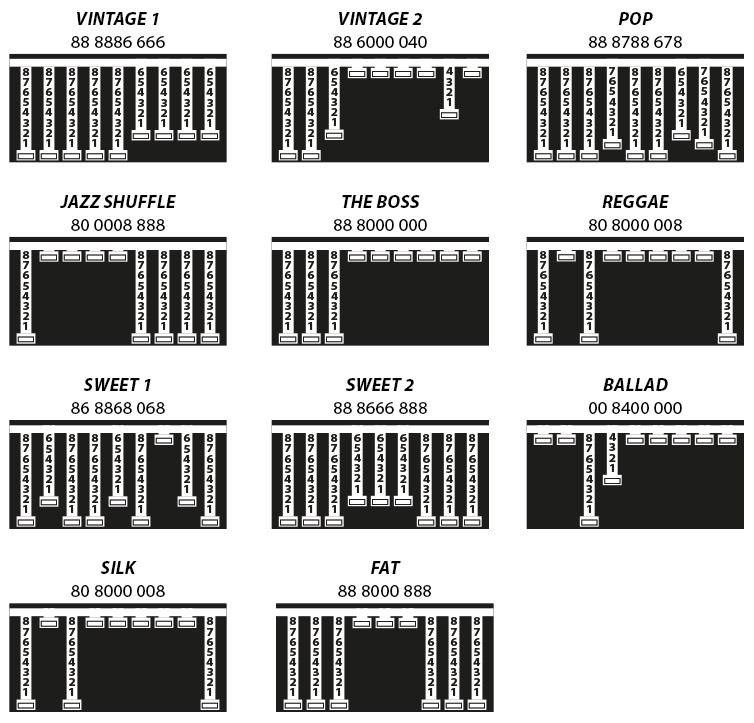
### Typical Drawbars setting
There are thousands of possible examples of Drawbars settings, made famous by organists during decades of live and recorded Organ music, and you can find below some of the most popular jazz, pop, gospel and rock settings.
The use of a Percussion or the addition of a Chorus or Vibrato effects can be added to your taste and you can find other examples in the Factory Programs, that you can also keep or modify to your taste.
There are many books suggesting Settings for all kinds of music, but the main feature of the Drawbars is the total freedom they allow you to use, to get the sound you like as well as “morphing” from one setting to another also with slow and smooth Drawbars movements, that are part of the beauty of this Organ Model.
### Original Drawbars settings
In the Vintage Tonewheel Organs , mainly in the Consolle versions (2x61 notes keyboard) the last octave on the left was made with reverse colors, since those keys were dedicated to the selection of factory presets, in addition to them selection of the 2 live Drawbars groups available for each keyboard (named Swell and Great as in the Pipe Organs.
At that time the Pipe Organ builders association tried to prevent, through legal actions, that electromechanical instruments (and any other electronic instrumet) could be called Organs and used also in churches for religious services; for this reason one of the attempts made by the manufacturers of electromechanical instruments was to simulate the sounds of the pipe organs and to name the factory preselections with typical names of the classical organ combinations.
The offficial test took place in the presence of legal and musical representatives in USA and saw the electromechanical instruments winning the challenge and being allowed to be called Organs.
The Factory settings of the Drawbars levels were mainly intended to imitate some typical pipe Organ sounds and they were hardware wired settings, that could be modified only by expert technicians.
The following are few examples of the millions of possible combinations.
| | |
|---------------------|-------------|
| French Horn | 00 8740 000 |
| Tibias | 00 8408 004 |
| Clarinet | 00 8080 840 |
| Novel Solo | 08 8800 880 |
| Theater Solo | 60 8088 000 |
| Oboe Horn | 00 4685 300 |
| Full tibias | 60 8807 006 |
| Trumpet | 00 6888 654 |
| Full Theater Brass‘ | 76 8878 667 |
| Stopped Flute | 00 5320 000 |
| Dulciana | 00 4432 000 |
| French Horn | 00 8740 000 |
| Salicional | 00 4544 222 |
| Flutes | 00 5403 000 |
| Oboe Horn | 00 4675 300 |
| Swell Diapason | 00 5644 320 |
| Trumpet | 00 6876 540 |
| Full Swell | 32 7645 222 |
### Chorus and Vibrato
The original vintage Tone Wheel instruments (not all the models) had a special and very complex circuit called Scanner Vibrato to add to the sound a very nice simulated frequency and phase modulation, that became another typical effect of these instruments. This particular post-processing is also part of the Organ Model and with the dedicated buttons you can choose from 2 Vibrato or 2 Chorus effect settings and assign them to one or both parts. To do this you can select the focus position pressing Upper and/or Lower and control the effects, in all details and separately for the 2 parts.
### Percussion
To add more rhythmic elements to your performance you can switch on the Percussion, another very typical and important feature of the vintage electro-mechanical organs, included in the Organ model. This effect only retriggers when all keys are released before, allowing to control the effect by playing “legato” or “staccato”. Playing legato, the Percussion will work only on the first notes played and it fades away during the decay, allowing to make short and aggressive solo parts followed by legato chords or scales, without Percussion.
You can press the On/Off butto to activate Percussion and select the 2nd/3rd button to decide if the Percussion is generated by the second harmonic, equivalent to the 4’ Drawba), or by the third harmonic, corresponding to the 2 2/3 Drawbar.
The Slow/Fast control defines the decay of the Percussion and the related Volume can be separately controlled in the related page of the GLOBAL Edit.
As explained in another part or this manual, the original Tonewheel Organs had a direct panel control for the Percussion Volume, but it was made only of two possible settings: SOFT or NORMAL. In the Global parameter you have a continuos control on the Percussion level with 64 values, indipendently associated to the Fast and Slow decay.
## Synth Engine
The Synth Sound Bank is bases on a simplified Synthesis engine, with the following features:
### Waveforms
The selection if various Waveform is made by selecting one of the Sounds of the Synth Bank; the various waveforms shape is shown on the display when the Sound is selected and can vary from the standard Sawtooth and Square Waves, to the Pulse with Modulation (a Pulse waveform with a modulated with by a low frequency modulator) and FM or complex Synthesis waveforms.
The Synth Sounds (basic or complex) are controlled by the nine Sliders, each one assigned to control a specific parameter, that allows to modify slightly or completely the starting selected Synth Sounds.
### Cutoff
Controls the frequency for the 2 poles low pass filter, use lower values in the range o to give more warm spectrum to the sound; at higher levels the sound becomes more brilliant, as the filter let pass thru it all frequencies of the selected Waveform of the starting sound.
### Resonance
When the setting is raised to mid-hi values, the filter starts to emphasize the frequencies around the Cutoff value; this feature can be used to create analog-style effects, as well as make a part of the Sound spectrum emphasized by an accurate setting of the Resonance.
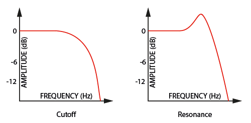
If set at values too close to the maximum, the Resonance could create a signal level gain and consequent distortion possible problems of the overall sound; with hi levels of Resonance, the part Volume (Upper or Lower) should be reduced proportionally, to avoid clippings or unwanted side-effects.
Both Cutoff and Resonance parameters are enabled to control any other Sound of the instrument (not only Synth Sounds) making possible to edit the starting sound, as an example make a Strings sound mellower or an Electric Piano sound emphasized at the Cutoff Frequency with the addition or a certain level of Resonance. As mentioned before, with some setting of the Cutoff + Resonance you might have to re-balance the part Volume, to avoid clippings of unwanted side-effects, unless you want to reach a certain sound that could also include some clipping as a desired effect.
### Filter and Amplitude Envelope
A typical Synthesizer section is made of controls named ADSR (Attack, Decay, Sustain, Release) and they are normally duplicated for the FILTER and the AMPLITUDE controlled sections.
The simplified available parameters are a sub-set of these controls, selected from the ones more effective in the instrument’s SYNTH engine sound generation.
The ATTACK Slider controls the time that the FILTER needs to reach the desired CUTOFF starting frequency.
The DECAY Slider controls the time that the FILTER needs to reach the final CUTOFF frequency, when the keys are kept played.
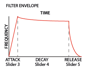
As a simplified setting, the DECAY also effects the SUSTAIN Level (a parameter not listed within the nine Sliders) and a long DECAY time will also simulate the final Cutoff Frequency almost identical to the starting frequency: the sound will not change after the ATTACK, while keeping the note played, or it will change very slowly.
The RELEASE Slider controls the time needed by the FILTER to reach the final Cutoff when the Keys are released.
The LFO Rate and Speed allow to control the related parameters of the LFO that is internally assigned to the CUTOFF Frequency; as an example, setting the values in a certain way, while the Resonance is set to mid-hi levels, could create SOUDS with a kind of looping WOW effect.
This LFO’s destination is the FILTER, while the Modulation (Vibrato etc) is controlled either by the STICK 2 and the AFTERTOUCH, allowing to select all possible combinations of all settings.
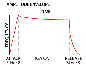
The last two sliders are controlling the ATTACK and DECAY of the AMPLIFIER and they do not change the FILTER parameters, that have separate A/D/R controls; they are able to create Slow attacks and Long release effects, without any change on the FILTER settings.
Please note that the A/R Amplifier control are the final block of the SOUND Synthesis chain; as an example, if you want a long Release on the FILTER you also have to set a long Release on the Amplifier, to make possible to hear the Filter Release when the keys are rereleased, and so on.
### Portamento
Also known as 'glissando' or 'glide'. If you play one note after another the pitch changes gradually at a predetermined rate from the first pitch to the second in a max range of 3 octaves.
There are 3 fixed Portamento time and one programmable value in Program Edit settings.
### Mono/Poly
This selection allows to select a monophonic mode for all SYNTH Sounds, allowing to play better solo parts and use the Portamento more effectively.
### Legato/Staccato
A musical articulation control which allows to get the selected PORTAMENTO on any new key or only when playing LEGATO mainly when playing solo parts in MONO mode.
## Effects
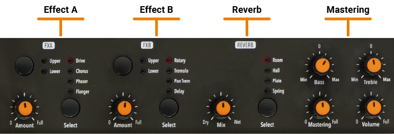
### FX1 - FX2
The 2 double effects processors allow to assign 2 separate effects to the Lower and Upper sections, for a total of 4 different effects at once. As an example, the FX1 can be set to Drive for the Upper section and, at the same time, to Chorus for the Lower section. Using the Upper/Lower button, you can toggle between the related parts and show or select the effect for that part. In addition, you will see or change the associated FX using the 2 main LOWER and UPPER buttons below the display.
You can visualize the Sound and FX structure and signal flow as it follows:
Upper > FX1 (one of the four) > FX2 (one of the four) > Reverb (programmable send in Edit)
Lower > FX1 (one of the four) > FX2 (one of the four) > Reverb (programmable send in Edit)
Amount: the 2 potentiometers control the Amount of the selected effect, like the dry/wet ratio (for modulating effects like the Chorus) or other parameters, like the distortion level of the DRIVE effects.
### Mastering
A post processing effects which enhanced the stereo width image and smoothly compress the sound.
Suggested settings:

## Global edit
To enter the GLOBAL edit, keep pressed the EDIT button for a few seconds; you will find various pages (shown on the top right area of the display) with functions that will affect the instrument, regardless what Program is selected. To escape from the function, press again the EDIT button and all settings will be memorized automatically.
When the focus (cursor) is on the top area of the display, rotating the encoder you can select the various pages; clicking on the cursor, the focus will be moved on the parameter and rotating the encoder you can change the related value.
The GLOBAL EDIT main functions are:
#### NAVIGATION 
See [Panel - display and navigation](#panel---display-and-navigation)
#### TRANSPOSE 
You can transpose the instrument to any other key; click on the encoder to move the cursor on the value and rotate it to input the desired transposition range.
#### GLOBAL TUNER 
This function allows to “tune” the instrument, in case you have to play along with another instrument that is not tuned to the standard (A=440 Hz).
RANGE: 415,7 - 466,2 Hz
#### VELOCITY CURVE 
You can select a different velocity curve, according to your taste and playing technique. There are 3 factory curves (SOFT/NORMAL/HARD) and a programmable FIXED velocity setting, with the related value.
#### FIXED VELOCITY 
You can set here the fixed velocity value (from 1 to 127) when the FIXED velocity is selected.
#### STRINGS RESONANCE 
Here you can control the amount of the STRINGS RESONANCE post-processing, that adds a more realistic effect to all Acoustic PIANO sounds.
#### DUPLEX RESONANCE 
It reproduces the resonances of the top right section of Acoustic pianos where there are no dampers and the strings can resonate also without pressing the damper pedal.
#### HAMMER NOISE 
It Reproduces the subtle noise of the hammers when they return to the rest position and it changes according to the speed at which the keys are released.
#### DAMPER NOISE 
It simulates the typical noise of the Damper Pedal on Acoustic pianos and it is velocity sensitive if controlled by the optional pedal SLP3-D.
#### SPEAKERS 
Change the speaker behavior.
Please note that the speakers require that the external power supply is connected.
- OFF: Speakers always off.
- AUX: Speakers always on.
- AUTO: The speakers are automatically turned off when you plug the headphones.
#### PEDAL 2 
While the PED1 is always suitable for expression-volume pedals, the PED2 can be programmed to connect almost all possible pedals, as it follows:
- SINGLE SWITCH normally open;
- SINGLE SWITCH normally closed;
- EXPRESSION (volume function, pedals with potentiometer and stereo plug);
- SLP3-D – Triple pedal with Soft/Sostenuto/Sustain function with half-damper control.
- PNO to manage the Soft/Sostenuto/Damper functions from the pedals.
- PRG which allows to change Programs up/down from pedals 1 and 2.
#### FX AUTOSET 
This function automatically assign a specific FX for some sounds and also memorize the last manually selected FX1-2 for each sound.
This real-time function will also control the association between the Stick2 and the Sound or FX controls (modulation or effect speed etc) in a logic and automatic way. When a particular FX is selected on a section, the Stick 2 will control a particular parameter, like the Slow/Fast speed of the Rotary or the Speed and Feedback of the Phaser.
The control will also be automatically set according to the focus position: if you have a Lower part without FX and the focus on Lower, the Stick 2 will control the Modulation; if the focus is on Upper and you have an Organ sound with Rotary, the Stick 2 will control the Rotary Slow/Fast speed.
If the FX Autoset function is set to off (see the GLOBAL Edit section) the function of the Stick 2 will be under Part EDIT, with not automatic assignments, and you can store all settings in each Program.
With the FX Autoset off, the automatic association between each sound and the last selected FX will be disabled and the FX selection will be only manual or controlled by the FX setting stored in each of the 99 Program.
#### LOCAL CONTROL 
This command is also received via MIDI and it is automatically deactivated the next time the instrument is turned on; in LOCAL OFF the keyboard does not send the notes played on the keyboard directly to the internal Sounds, but only via USB-MIDI to avoid unwanted repetitions when using external Software Programs which receive the notes from the keyboard and send them back to the generation.
#### USB MIDI OUT 
MULTI Ch: the instrument continues to work in its standard mode, sending notes and controls via USB on the respective MIDI Channels 1-2 of the enabled sections and on the COMMON channel 16 only the general controls.
SINGLE Ch: the control panel controls and the notes played on the keyboard are transmitted via USB on a single channel COMMON = 16
#### MIDI MERGE 
The merge function allows to merge-mix the MIDI IN data to the local MIDI data (notes, controls etc) and send the result to the USB and/or MIDI Out; the selectable options are:
- OFF = Merge function disabled
- TO MIDI = Merged MIDI data are sent to the MIDI OUT
- TO USB = Merged MIDI data are sent to USB
- TO MIDI+USB = Merged MIDI data are sent to both USB and MIDI Out
#### SYSEX FILTER 
To filter (cut out) some MIDI message (besides the standard ones) when merging a MIDI in source to the selected destination.
#### SLIDER MODE - DIRECT/SNAP 
The 9 Sliders (Drawbars in Organ mode) can have two different way of operate, to be selected in the related Global Edit page, according to your preferences and playing needs.
Selecting the DIRECT mode, when a Slider/Drawbar is moved, the new value corresponding to the physical position is immediatly read and sent to the Sound generation, allowing to instantly input the new value, from 0 to 8 in Drawbars-Organ mode and from 1 to 127 in Slider mode, either for Synth parameters and MIDI assignable values.
Selecting the SNAP mode, when a Slider/Drawbar is moved, new values are read and updated one after the new position corresponds to the original stored value; as an example, if the Cutoff value of a Sound was 100, the Slider will input a new value only after you reach the original 100 position.
#### CLICK KEY ON / CLICK KEY OFF 
The Key Click adds the typical noise associated with the tone wheels vintage organ's technology that became part of their sound. With the related Key ON and key OFF controls you can set the level of the noise according to your taste: this Global Edit function allows to control the Click level separately for Key on and Key Off, in order to reach the desired effect when playing the keys and when releasing them.
#### FAST/SLOW PERCUSSION VOLUME 
This GLOBAL function allows to control the Percussion Volume; the original Tonewheel Organs had a direct panel control for the Percussion Volume, but it was made of 2 steps: SOFT or NORMAL- With this Global parameter you have a continous control on the Percussion level with 64 values, independently associated to the Fast and Slow decay.
#### LEAKAGE 
New implementation relating to the ORGAN model with continuous control from 00 to 127 which reproduces in each Drawbar, the harmonics due to the electromagnetic interference (crosstalk) between the adjacent tone wheels as well as the signal passage between the numerous wiring harnesses of the original instruments. Leakage affects both Organ Models.
#### ROTARY FAST 
MIN/MID/MAX selection of the upper part of the upper rotor of the Rotary, referred to the three pulleys available on the original Leslie. This control allow to vary the maximum speed based on which pulley is connected to the drive belt.
#### PROGRAM BULK (legacy)  
This function has been integrated into the Numa Manager application. However, if you still want to use the legacy method, do the following:
- Connect the Numa Compact to your computer via USB;
- Open an application that can send/receive Sysex messages;
- Once the function is selected, rotating the encoder to choose SEND or RECEIVE;
- Select Numa Compact as target device;
- To send data to your computer, click the encoder when selecting SEND, confirm YES and wait until is done;
- To receive the data back to your instrument, click the encoder when selecting RECEIVE; then send the Sysex file through the application.
#### FACTORY RESET 
The Factory Reset is divided into:
- PROGRAMS: which restores all Programs to factory settings.
- GLOBAL which restores all parameters except the Programs.
It could make you lose custom settings or programming and the function should be done very carefully. To protect the user from unwanted reset, a caution YES/NO message appears when trying to reset the unit, allowing to confirm or not the factory restore.
#### FIRMWARE VERSION AND UPDATE 
Check the firmware version.
Firmware update instructions
## Program edit
If the focus (cursor) is on the upper part of the display on Programs selection, pressing the EDIT button will enable the Program Edit, with the following parameter and settings.
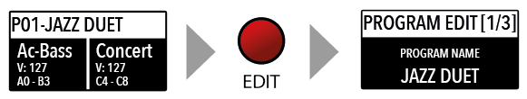
Program edit is common for SOUND and MIDI; it refers to general parameters associated to both the SOUND and MIDI sections.
#### PROGRAM NAME
After having selected this function, click on the encoder and input the letters of number rotating it; a small triangle will show what digit you are editing.
To confirm the new name or keep the previous, press STORE and a popup window will ask you to confirm the change or not, rotating the encoder to YES or NO and confirm by clicking.
#### SPLIT POINT
This function allows to select the SPLIT point for each PROGRAM, by rotating the encoder till the desired note is shown. Please note that, as per international standard, the instrument keyboard is named from A0 (first key on the left) to C8 (last key on the right) and consequently the middle C below the display is C4. The reference pitch of A=440 Hz is on A4, the A of the same octave of C4 (below the sound banks) for all sounds that are based on the standard 8’ of the piano range. Only some ORGAN sounds will play one octave below, if based on a 16’ pitch drawbar of the vintage tone wheel organs or the related Pipe Organs 16’ classic organ stops; in these cases the foundamental of the selected sound on A4 will be 220 Hz (one octave below 440 Hz).
#### MIXER
The Mixer allows to control all four parts and zones (LOWER/UPPER/ZONEA/ZONEB) at once, in a single organized page. This function can also be accessed with a shortcut, keeping pressed the SPLIT button also marked MIXER with brackets.
#### ORGAN MODEL
It allows you to select two options:
- TONEWHEEL which corresponds to the typical sound of vintage B3-type models.
- ELEKTRO less sinusoidal sound, similar to the Principals or Diapasons of classical organs as they were made in electronic simulations, also suitable for reproducing the timbres of the non-electromechanical Electronic Organs of the 60s and 70s thanks to the control of the Drawbars, Percussions, Leakage and Rotary.
#### ROTARY OVERDRIVE
Tube-like distortion with control from 00 to 127, exclusively applied to Rotary. It is important to note that the distortion, unlike what happens for the DRIVE of FX-A, does not change with the volume of the section or with the Expression pedal and remains adjusted as per parameter, to add a fixed tube effect to the Rotary simulation.
#### ROTARY MIC POSITION
CLOSE/FAR simulates a position of the microphones close or far from the original cabinet, which affects the depth and spatialization of the modulation. By selecting CLOSE, the modulation amplitude is maximum, while on FAR it is reduced, as occurs by moving the real microphones away from the cabinets.
#### ROTARY MIC SETUP
- MONO equals just 2 microphones placed at the top and bottom of the cabinet.
- STEREO is equivalent to 4 microphones positioned two at the top and two at the bottom
By selecting the MONO setting, we recommend choosing the Mic Postion FAR to prevent the modulation from being excessively deep and also to simulate the typical sound of amplifications generally used in live performances, while the STEREO settings are mainly used in studio recordings.
#### ROTARY SLOW/FAST
Rotary speeds can now also be selected from PED2. Manually assignable in EDIT MENU or automatically with FX Autoset active. FX Autoset switches the function of PED2 according to the selected SOUND and relative FOCUS of the ZONE.
## Part edit
If the focus is on one of the parts and you are in SOUND mode (with the SOUND button selected and lighted) you will enter in the PART edit mode. When you have selected PART edit you can always press the LOWER or UPPER buttons to select the part to be edited, or click on the encoder.
The PART EDIT includes the following parameters:
#### VOLUME
Rotating the encoder, after having moved the focus on the parameter by clicking on it, you can control the selected part Volume, in a range from 0 to 127.
#### SPLIT ASSIGN
Once you have selected the SPLIT point for the current PROGRAM (ref: PROGRAM EDIT) you can decide where the selected LOWER or UPPER section (either for the SOUND and MIDI zones) should play, in a totally independent way as it follows:
- TO LEFT: the part will play to the left section of the keyboard (from A0 to the SPLIT note);
- TO RIGHT: the part will play to the right section of the keyboard (from the SPLIT note to C8);
TO ALL: the part will play with no split all over the keyboard.
This function will allow many musical combinations, such as the few following examples and their opposite settings:
PIANO on the right + BASS on the left, of the split point;
PIANO and STRINGS on the right + MIDI ZONES on the left (controlling external devices);
ORGAN on the entire keyboard (TO ALL) and CHOIR on the right part only.
Even with one SPLIT point (programmable for each PROGRAM) the possible settings are almost one hundred, considering the status and combinations of LOWER+UPPER+ZONEA+ZONEB and the SPLIT settings made possible by this function.
#### TRANSPOSE
This function allows to transpose a part; differently from the GLOBAL TRANSPOSER, that will effects the entire instrument, this function can be set independently for each SOUND section or MIDI zone and stored in each PROGRAM, with different values. Interesting combinations are obtained by transposing a sound with musical intervals, like a lower quint = minus 5 semitones, to get what is commonly known as a “cluster” with fixed intervals. Try to select a TRUMPET on UPPER and a SAX on LOWER, setting the SAX 5 semitones lower, in a typical JAZZ setting.
#### OCTAVE
You can set the octave (intervals of 12 semitones each) separately for each part; normally you will need to move a LOWER part one or two octave up, if you want to play chords in a better range. On the other way, sometimes you can get a better sound, when the SPLIT is activated, if you move the UPPER part one or two octaves down, as you could prefer if you select a TENOR sax in combination with a splitted BASS sound on the left, since the Sax lower and nicer notes could probably be on the left of the splitted keyboard portion. Simply experiment the setting you prefer and then store it in the current PROGRAM.
#### FINE TUNE
This parameter allows to fine-tune the Upper and Lower sounds within a semitone range; it could be useful to create “beating” sligthly detuned sounds, when assigning a pure Waveform to both sections (i.e. Sawtooth, Square etc) or enhance some Orchestral 2 sections mix, making it richer.
#### REV SEND
The function allows to control the amount of signal to be sent to the REVERB processor, independently for the LOWER and UPPER parts and programmable with different settings for each PROGRAM. As a typical setting, if you SPLIT the keyboard and assign a BASS sound to the left, you might want to reduce or minimize the amount of REVERB on the left part, or control the setting also on the UPPER part to get the desired effect. The MIX potentiometer, on the front panel, will change the overall reverberation mix (Dry/Wet) with any reverb type selected or send value.
#### PEDAL 1 / PEDAL 2
Here you can decide if the pedals are enabled or not for each section (UPPER/LOWER or ZONEA and ZONE B if the MIDI button is activated).
#### STICK 1 / STICK 2
As for the pedals, also the Sticks can be enabled separately for the Parts and Zones; please note that the Stick 2 will be set automatically to AUTO if the related FX-AUTOSET function is set to ON in the GLOBAL EDIT area. To control the Stick 2 assignment manually, you can set to OFF the FX-AUTOSET and the function can be switched ON or OFF and stored in the Programs.
#### AFTERTOUCH
This parameter enables or disables the aftertouch function on the selected Part or Zone; the function of the Aftertouch will be in most cases similar-same of the Stick 2 modulation control, adding some kind of vibrato or similar modulation to the sound, according to the setting. Normally you will set the Aftertouch ON for the UPPER part, that is commonly used for the main musical part or solo performances, while the LOWER part is normally associated to accompaniments or bass lines, if the SPLIT is active.
#### TINE
This parameter controls the attack transient harmonics of the most Electric Pianos, with the typical bell type sound or mechanical noise associated with the original vintage instrument.
#### PORTAMENTO TIME
This parameter allows to set any value of Portamento between 0 and the maximum available time.
## MIDI
Numa Compact SE has a complete MIDI Implementation, that includes 2 separate software MIDI Ports, that you can see connecting the instrument with the USB Cable to your computer, named KEYBOARD and CONTROLLER ports.
The KEYBOARD port is programmed to send and receive all MIDI controls related to the internal SOUNDS, EFFECTS and PROGRAMS, allowing to control all functions of the instrument, sending and receiving what you physically do on it, from the notes you play on the keyboard, to the SOUNDS you select on the 2 local sections (Upper and Lower) and for the other 2 additional sections (Part3 and Part4) that can be played via MIDI. Via MIDI you can also set the Part 3 and Part 3 SOUNDS and Reverb levels (they cannot be sent to the internal Effects) creating a total of 4 parts MIDI Sequence.
As example you can play a Drums & Bass groove on MIDI CH3 and 4 and record a live part on UPPER and/or LOWER, creating a 4 part arrangement of any kind.
The four KEYBOARD Parts have a separate MIDI Channel each one, corresponding to the following MIDI structure:
**KEYBOARD MIDI PORT**
- Upper = MIDI Ch1 (send and receive)
- Lower = MIDI Ch2 (send and receive)
- Part 3: MIDI Ch3 (receive only)
- Part 4: MIDI Ch4 (receive only)
All real time Panel controls (Organ Drawbars and Synth Sliders, SOUNDS, FX selection and related Amounts and settings etc) are sent and received, as listed in the MIDI IMPLEMENTATION CHART.
The last four potenziometers are only for local settings (VOLUME, MASTERING, BASS & TREBLE) as they should not be sent or received via MIDI.
Anything you control and play on the Numa Compact can be transmitted, recorded and received via MIDI, allowing a full control of all functions.
The second separate MIDI PORT is dedicated to the CONTROLLER section (ZONE A and ZONE B) and thru this separate PORT you can send all MIDI controls related to the MIDI Zones and their related settings, controls, Stick functions (Pitch and Modulation, as well as the Aftertouch) etc.
Being this PORT 2 related to the MIDI function, the IMPLEMENTATION only includes the SENT MIDI Messages, while no MIDI controls are needed and implemented as MIDI IN.
As esplained this double KEYBOARD/CONTROLLER PORT structure is meant to be used when a MIDI-USB connection is made with a Computer.
As explained in the GLOBAL EDIT parameters, the COMMON Midi channel allows to send all incoming MIDI data (notes etc) to the main instrument’s section, allowing to change the main PROGRAMS and play the instrument’s UPPER and LOWER parts as you would play on the local keyboard (with Split or Layers, the related key range etc).
Connecting the Numa Compact via MIDI OUT (not USB) the instrument only transmits the implemented CONTROLLER messages when you connect a physical MIDI cable to the MIDI OUT socket.
## Zone edit
If the focus is on one of the zones and you are in MIDI mode (with the MIDI button selected and lighted) you will enter in the ZONE edit mode; when you have selected ZONE edit you can always press the ZONE A or ZONE B buttons to select the zone to be edited, or click on the encoder to move the cursor/focus as for all other instrument's functions.
The ZONE EDIT includes the following parameters:
#### PROGRAM CHANGE
Here you can input the Program Change number of the controlled device or sound generator, referring to the specific Sound Map of the connected device/vst/sound generator. The value range is 1-127.
#### LSB - MSB
LSB stands for Least significant Byte, MSB stands for Most significant byte and they allow to control and select more banks of the standard 127 Program Changes or many other functions, defined by the MIDI standards; to input the correct numbers, you have to refer to the implementation chart of the controlled device, where each Sound is defined with the MIDI data to select and control it.
#### MIDI CHANNEL
You can select the MIDI channel (value 1-16) for each Zone, to control 2 different external devices or sound generators.
#### VOLUME
Rotating the encoder, after having moved the focus on the parameter by clicking on it, you can control the selected part Volume, in a range from 0 to 127; the Zone volumes can be controlled directly also not in EDIT mode, when the MIDI button is lighted and the cursor-focus is on one of the Zones.
#### SPLIT ASSIGN
Once you have selected the SPLIT point for the current PROGRAM (ref: PROGRAM EDIT) you can decide where the selected ZONE should play, in a totally independent way as it follows:
- TO LEFT: the zone will play to the left section of the keyboard (from A0 to the SPLIT note);
- TO RIGHT: the zone will play to the right section of the keyboard (from the SPLIT note to C8);
- TO ALL: the zone will play with no split all over the keyboard.
Even with one common SPLIT point (programmable for each PROGRAM) the possible settings are almost one hundred, considering the status and combinations of LOWER+UPPER+ZONEA+ZONEB and the SPLIT settings made possible by this function.
#### TRANSPOSE
This function allows to transpose a Zone; differently from the GLOBAL TRANSPOSER, that will effect the entire instrument, this function can be set independently for each MIDI zone and stored in each PROGRAM, with different values.
#### OCTAVE
You can set the octave (intervals of 12 semitones each) separately for each Zone; normally you will need to move a zone one or two octave up, to the LEFT Zone of a split keyboard, to play chords in a better range. On the other way, sometimes you can get a better sound if you move the UPPER zone one or two octaves down; simply experiment the setting you prefer and then store it in the current PROGRAM.
#### PEDAL 1 / PEDAL 2
Here you can decide if the pedals are enabled or not for each Zone independently, according to where the cursor-focus is set (on ZONE A or ZONE B).
#### STICK 1 / STICK 2
As for the pedals, also the Sticks can be enabled separately for the Zones; please note that the Stick 2 will be set automatically to AUTO if the related FX-AUTOSET function is set to ON in the GLOBAL EDIT area. To control the Stick 2 assignment manually, you can set to OFF the FX-AUTOSET and the function can be switched ON or OFF and stored in the Programs.
#### AFTERTOUCH
This parameter enables or disables the aftertouch function on the selected Zone; the function of the Aftertouch will be in most cases similar-same of the Stick 2 modulation control, adding some kind of vibrato or similar modulation to the sound, according to the setting. Normally you will set the Aftertouch ON for the UPPER zone, that is commonly used for the main musical zone or solo performances, while the LOWER zone is normally associated to accompaniments or bass lines, if the SPLIT is active, however the setting is totally under your control and choice.
#### Sliders Programming
Selecting one of the pages dedicated to Sliders programming, moving one of the Sliders will automatically enable the selected editing for that Slider; repeating the procedure for each Slider will allow you to make the complete Sliders programming, for the various functions and settings.
All sliders settings can be memorized in any Programs, with same procedure of the Store Function.
- **CC SLIDER**
This page allows to select the CC function for each one of the nine sliders, some selection is only numeric, if the related CC is generally undefined by a standard, while others are also referring to the name of the function, in addition to the number, such as cc 64 = Damper etc.
- **MIN SLIDER**
Selecting this function, for each slider, you can decide the MIDI value sent by the Slider when is moved on the lowest position, (with the function programmed in the page CC Slider).
- **MAX SLIDER**
Selecting this function, for each slider, you can decide the MIDI value sent by the Slider when is moved on the top-highest position.
The MIN and MAX Sliders values determine the total range of the selected function, as well as the direction of the programmed control.
Setting the MIN Slider to hi values (for instance 127) and the MAX Slider to lower values (for instance: 0) the result is a reversed control, from MAX (top position) to MIN (lowest position) as can be requested to control Drawbars settings of some Organ VST on your computer.
These settings allow to create for the MIDI Sliders similar functions of an ORGAN or SYNTH sound, where the Drawbars and Sliders are automatically associated to the selected Sound, with the related MIN/MAX different positions; to increase the Drawbars volume you will pull down the sliders, while the selected Slider’s function will increase moving the slider to the top position.
## Precautions
***Always follow the basic precautions listed below to avoid the possibility of serious injury or even death from electrical shock, short-circuiting, damages, fire, or other hazards.***
#### Power supply
Do not place the product near heat sources such as heaters or radiators.
Use only the correct voltage specified for the product and the supplied power cord/plug.
#### Do not disassemble
This product contains no user-serviceable parts. Do not attempt to disassemble the internal parts or modify them in any way.
#### Humidity
Do not expose the unit to rain or moisture. Never place containers with liquid on the unit. Do not use the unit near water, a swimming pool, a bathtub, or a wet basement. If the unit is moved from a cold place to a warm room, condensation may occur inside. To avoid damage, please allow the unit to reach room temperature before switching it on. Never insert or remove a power plug with wet hands.
#### Installation
Always use a stable rack to place the product on. Please be aware of its size and weight.
Do not place the product in an unstable position or a location with excessive vibration.
Do not place other objects on top of the product.
#### Handling
Using near devices that emit radio signals may generate noise.
Do not expose the product to excessive dust, vibrations, or extreme cold or heat, such as direct sunlight, near a heater, or in a car during the day.
#### Cleaning / Maintenance
Never use any abrasive detergent, which may damage the surface. We recommend a slightly moist microfiber cloth.
#### Packaging
Please keep all packaging, and use it to protect the product when transporting or if servicing is required.
## Declarations
#### Warranty
Every product from Studiologic by Fatar has been carefully manufactured, calibrated and tested, and carries a warranty. Damage caused by incorrect transport, mounting or handling is not covered by this warranty. Compensation amounting to more than the price of the device is excluded. For any further informations please refer exlusively to your dealer and/or local distributor. This is based on general terms and condition of the local distributor / FATAR srl, Italy.
#### CE-Conformity
FATAR srl
Zona Ind.le Squartabue
62019 Recanati MC Italy
declares that this product complies with the European Directives:
2004/108//EC: EMC Directive
DIN EN 55013: EMC radio disturbance of sound, TV and associated equipment
DIN EN 55020: EMC immunity of sound, TV and associated equipment
Recanati, 02. 02. 2024 Marco Ragni, Chief Executive Officer
This declaration becomes invalid if the device is modified without approval.
#### RoHS-Conformity
This product is manufactured according to the 2002/95/EC directive.
#### Disposal / WEEE
The purpose of this EC Directive 2003/108/EC is, as a first priority, the prevention of waste electrical and electronic equipment (WEEE), and in addition, the reuse, recycling and other forms of recovery of such wastes so as to reduce the disposal of waste. Please help to keep our environment clean.
#### State of the art
To ensure maximum quality all Studiologic by Fatar devices are always engineered to be state-of-the-art products, therefore updates, modifications and improvements are made without prior notice. Technical specification and product appearance may vary from this manual.
#### Trademarks
All trademarks used in this manual belong to their respective owners.
#### Copyright
No part of this manual may be reproduced or transmitted in any form or by any means without prior consent of the copyright owner:
FATAR Srl
Zona Ind.le Squartabue
62019 Recanati, Italy
[Save as pdf](numacompactxse_manual_en.pdf)